RESULT
1. ORIGAMI OBSERVATION by AFM
All of the DNA structures were observed by an atomic-force microscope Multimode 8 (Bruker).
1-1. DNA origami
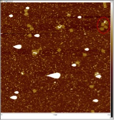
The AFM images of the origami alone are as below (Fig. 1).
 b.
b.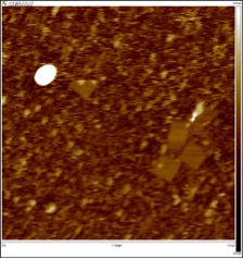 c.
c.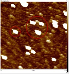
Structures of well-defined rectangular origami were observed (Fig. 1-a,b). They were just about the size we had expected (70nm x 100nm) as well. However, some samples showed origami that were all distorted very similarly (Fig. 1-c). This suggests the modification we made to the several staple strands might have had an effect on the proper formation of the structure. In addition to that, these origami were much larger both in area and height. Since some structures had twice the area of the supposed origami, there may be a possibility that several origami stuck on top of each other or sideways.
1-2. DNA origami with glue sequence strands
Images of origami when glue sequence strands were added are shown below (Fig 2). We let the glue strands react with the origami for 1 hour at room temperature before observation.
a.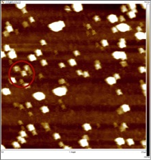 b.
b.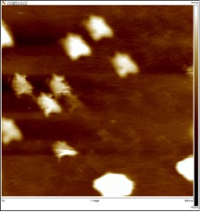 c.
c.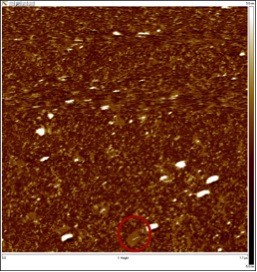
As seen in the images, the origami did not form a large sheet as we had anticipated; the maximum number of origami that were close to each other was 3~4 at the most. However, we noticed there was a large difference in the arrangement of origami when compared to the arrangement of origami lacking the glue strands. The wide-angle view of the origami (Fig2-a.) demonstrates this very well. You can see that almost all of the origami are facing the same direction. There is one more point that should be noticed. Most origami had a taller height than expected, which indicates the stacking of several origami on top of each other.
1-3. DNA origami with gold nanoparticles (AuNPs)
 b.
b.
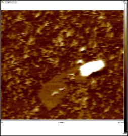
The detection and determination of AuNPs attached to sheet was not very easy. This was because the diameter of the particle was as small as 5nm, and because we did not have a clear image of how a gold particle would actually appear on the screen when attached to an origami. However, there was a significant difference in the appearance of the origami, and so we think AuNPs had at least some kind of effect on the formation of origami. Additionally, we observed many origami from which some small areas were sticking out, creating a white pattern on them. Although, the size of the white area is not close to the size of the AuNPs, we think the creation of the pattern is somehow related with the particles.
2. SPECTRUM MEASUREMENT
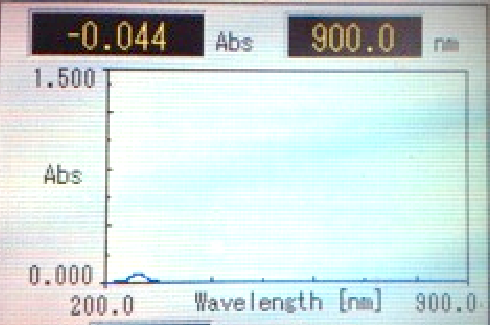
Absorption spectrum or the origami was measured with wavelength ranging from 200nm to 900nm (Fig 4).
 b.
b.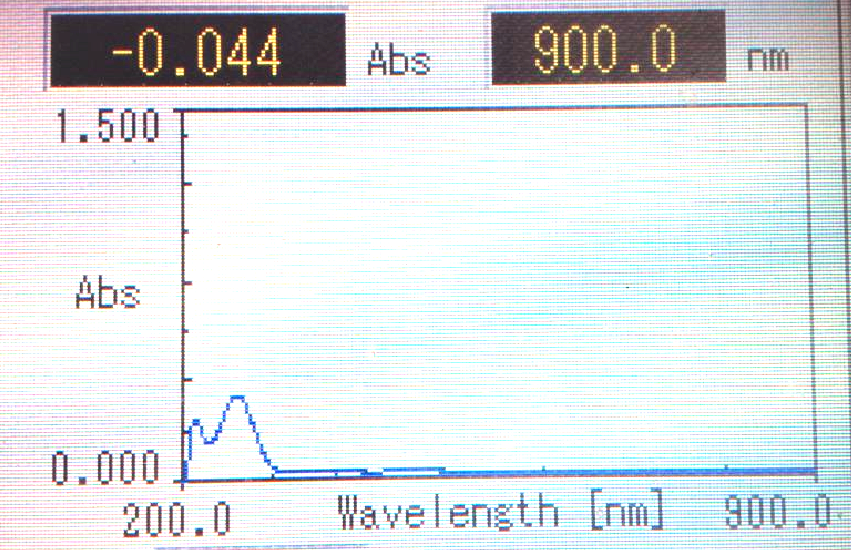 c.
c.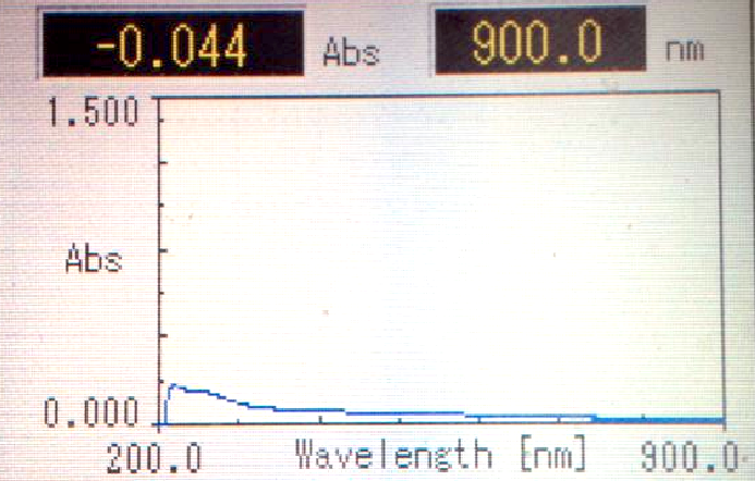 d.
d.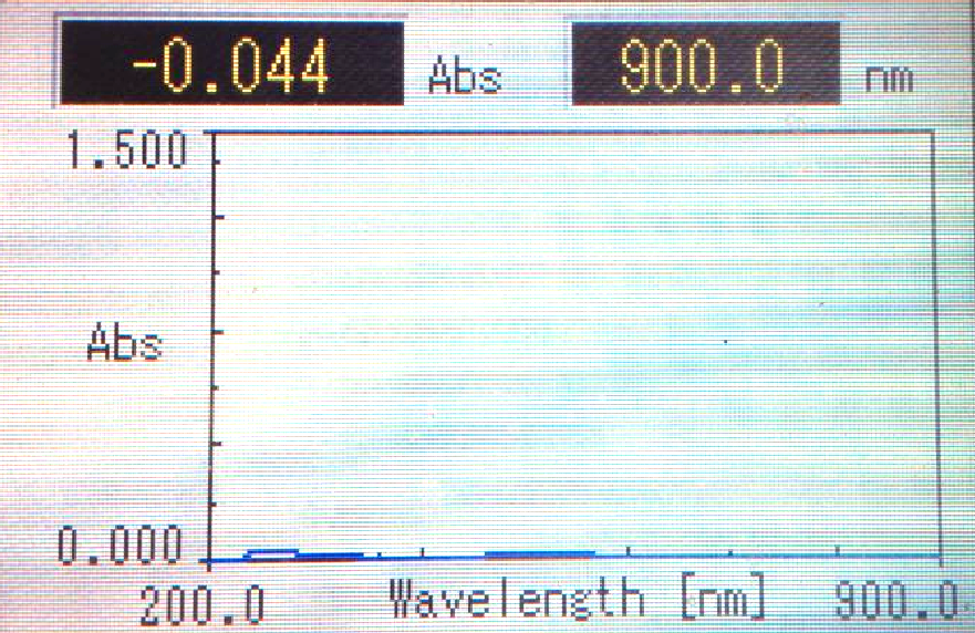 e.
e.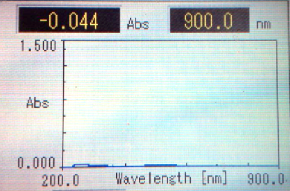
All of the samples except the gold nanoparticles itself showed a similar absorbance pattern in the range of 200-400nm, with a peak between 200nm and 300nm. The rest of the wavelength did not show any absorbance. Origami with glue strands showed the highest absorbance, while AuNPs without the origami hardly had any absorbance.
3. DISCUSSION
In this project, we aimed to synthesize DNA origami-attached AuNP and bind them each other to make a UV cutting sheet.
First, we succeeded to confirm some structure of DNA origami by AFM experiment. The structure of rectangular DNA origami was clearly observed. When we added glue DNA to the origami, we could see the change in origami arrangement. All of the origami were facing the same direction, and this seemed to occur by the binding effect of glue DNA. It was not a complete sheet we intended, but we can say that glue DNA has the ability to change the arrangement of origami rectangles and if we realize optimal conditions, we might be able to make a complete flat sheet. We also tried to add AuNP-oligo DNA to origami rectangles to arrange AuNPs on the surface of origami. As a result, we obtained an AFM image that looked like AuNPs were attached to origami. Although we could not predicate they were AuNPs, we have room for improvement to attach AuNP to origami. Of course, we have some problems. For example, in our design, when origami rectangles bind to each other through glue DNA, a slight distortion may happen. Also, we used spin columns to purify AuNPs-attached origami, but this might have been inappropriate, because the centrifugal force may cut the binding between origami and AuNPs. To certainly make an origami sheet, we should improve its design and experimental protocol. To sum up these AFM result, we can say that we achieved the initial accomplishment to make AuNPs-attached DNA sheet regularly.
Second, we carried out absorption spectrum measurement. We expected that absorbance from 200nm to 400nm rises in origami sheet with AuNPs. As a result, we observed rise of absorbance in this range with samples of origami+glue, origami+AuNPs and origami+glue+AuNPs. The solution containing only AuNPs did not show a rise in the absorbance. Initially, we focused on the AuNPs’ ability to absorb UV and regarded DNA origami sheet as a tool arranging AuNPs regularly on surface, but these results suggest DNA origami itself also has the ability to cut UV and AuNPs have little effect cutting UV without the origami sheet. This was an unexpected effect and we should think about both effects to improve UV-cutting ability of our sheet.
Now our project is at early stage of basic study, but we successfully made some accomplishment. For future work, we can improve efficiency of sheet-formation and enhance UV-cutting property by modifying our design and synthesis protocol.