interface version 1
Builds the bounding box for animated input geometry.
This operator can evaluate its input geometry over a frame range, merge it into a single geometry, and compute the resulting bounding box. The results are also returned as numeric parameter values (so they can be referred to in expressions, etc).
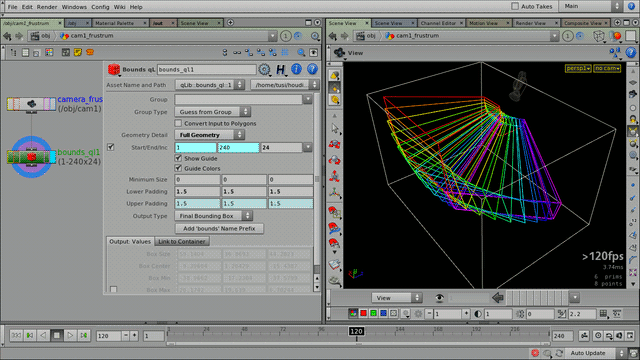
Bounds of the view frustrum of an animated camera: a common technique for determining the visible 3D area of a shot (used with a Camera Frustrum qL SOP). The color-code indicates the relative timing of each geometry snapshot.
This operator can be very useful for DOP solvers that have bounding box settings for spatial limits (e.g. fluids or volumetrics).
With this node, such limits can be easily approximated, even (especially) when considering animated geometry.
Currently this operator only calculates non-oriented bounding boxes.
Tip
A practical example: when doing fluid simulations, the bounding box size and center output values can be directly linked to the volume limit parameters of a Flip Solver DOP.
This allows for completely procedural simulation setups – no need to adjust the limits by hand after geometry or animation changes. (The bounding geometry itself could be constructed from actual scene objects that are involved in the simulation.)
Tip
For heavier geometry, use larger frame step values and “Bounding Box” detail mode. (You can also reduce the geometry detail by “manual” preprocessing before passing it to this operator, e.g. keeping only every n-th primitive, etc.)
Although the overall bounds computation might happen to be expensive, it also has to be computed once (unless the input geometry animation changes).
Parameters
| Group, Group Type | Allows to specify a subset of the entire geometry to work with. | ||||||||
| Convert Input to Polygons | The input geometry will be converted to polygons before the bounding box calculations. This can be useful when dealing with more esoteric geometry types (e.g. implicit primitives). | ||||||||
| Geometry Detail | The detail level of each individual geometry that will be merged together for the bounding box computation.
| ||||||||
| Frame Range (Start, End, Inc) | The input geometry will be evaulated multiple times within this range, the results merged, and from that will the final bounding box be computed. The frame step value is important: for heavier geometry, keep it as low as possible, but without losing detail from the animation (the visual feedback of the guide display can be helpful). (Usually it’s enough to sample every n-th frame – the results will still be acceptable, and with a much smaller speed/memory impact.) Also note that for all fields fractional values are supported (so non-integer frame step values are valid and allowed). | ||||||||
| Minimum Size, Lower Padding, Upper Padding | Adjustments to the final bounding box (see Bound SOP for details.) | ||||||||
| Output Type | Geometry to output: final bounding box, or the geometry “trail” the final bounds are computed from. The output values (below) are not affected by this setting. | ||||||||
| Show Guide | The guide display shows all the geometry that is merged together from the individual animation frames. It can be useful for adjusting geometry detail and frame step (Inc) settings. | ||||||||
| Guide Colors | The guide geometry will be displayed with a color gradient to indicate the movement of the trail over time. (The gradient is pink/blue-to-red, where the pink/blue is mapped to the beginning of the time range, and red is to the end.) | ||||||||
| Add 'bounds' Name Prefix | Adds the “BOUNDS_” prefix to the node name. (This allows easier picking of the node from an UI selection list – it also provides an unified naming scheme for Bounds nodes). | ||||||||
| Output |
| ||||||||
| Link to Container | This utility tab allows quick and easy copying (or connecting) of the boundary output values to any container (D)OP.
|
Release Notes
interface version 1 —
| 2014-05-07 |
|
| 2014-03-10 |
|
| 2014-01-16 |
|
| 2014-01-15 |
|
| 2013-09-15 |
|
| 2013-09-12 |
|
| 2013-08-27 |
|
| 2013-08-13 |
|
| 2013-05-08 |
|
| 2013-04-22 |
|
| 2013-04-18 |
|
| 2013-04-14 | The first frame of the range were often not added to the overall bounding box (the usual “remainder issue”). This is now fixed. |
| 2013-04-10 | First version. |