interface version 1
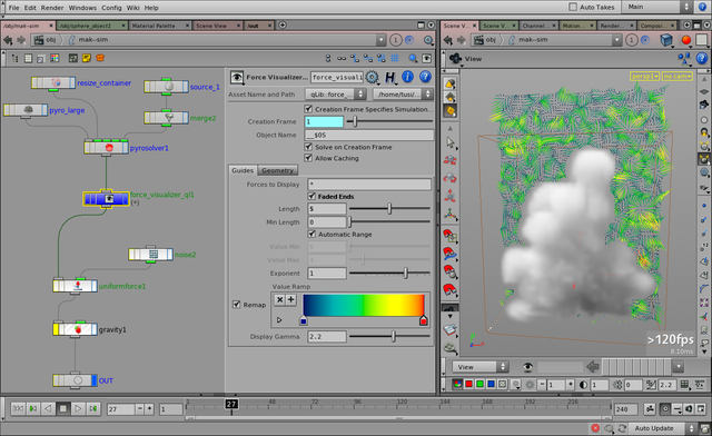
Visualization of the general DOP forces in the simulation.
This operator creates a DOP geometry for the visualization of the general (non solver-specific, or “external”)
forces within the simulation.
Note
This operator has to be placed before the force(s) to be visualized in the DOP graph.
Parameters
(Refer to the general DOP object help pages for parameters not described here.)
| Guides
| | Forces to Display
| A list (or pattern) of force names to visualize.
| | Faded Ends
| Visualization lines will have a slightly transparent end
(for the better indicating of direction).
| | Length
| Line length for the maximum force.
| | Min Length
| Minimum length for a visualization line.
| | Automatic Range
| The minimum and maximum values of all exerted force
(within the spatial area) will be automatically calculated.
| | Value Min, Max
| The force strength range that would be mapped to the color ramp
(if Automatic Range is off).
| | Exponent
| An additional bias for the color ramp
(to shift toward smaller/larger values).
| | Value Ramp
| The color ramp to use as indicator of force strengths.
|
|
| Geometry
| Settings for the geometry to be used as template source.
(The geometry points will be used as spatial points for the visualization.)
| Show Guide Geometry
| Show the original, “raw” input geometry (as a wireframe).
| | Animated Geometry
| If enabled, the visualization will get an update from the source geometry
on each new frame.
| | Geometry Source
| Source of the geometry.
(...)
| | Point Separation
| ...
| | Use Geometry Bounding Box
| ...
| | Use Plane, Plane Position
| ...
|
|
Release Notes
interface version 1 —